- PROTEUS 8 PROFESSIONAL PCB LAYOUT GENERATOR
- PROTEUS 8 PROFESSIONAL PCB LAYOUT FULL
- PROTEUS 8 PROFESSIONAL PCB LAYOUT SOFTWARE
- PROTEUS 8 PROFESSIONAL PCB LAYOUT FREE
Select your width according to the PCB you design. Selecting these buttons will open a new window. Select ‘track mode’ and you can change the track width by selecting ‘C’ (Create) or ‘E’ (Edit) as shown. You can change position by clicking on ‘selection mode’ and then selecting your component, you can then drag it to the required position. After adding all the components, arrange the components properly. Next, click on the component and rotate if required using rotate buttons, then place into your workspace. Once you’re done, click once again and the green line will change into a yellow colored layout. Click on ‘select layer’ and then select ‘board edge’. Now we will create our board edge using ‘2D Graphics Box Mode’. This will open a window with components list. First you will open Proteus and select ‘Tools’ and then select ‘netlist to Ares’. Proteus has an integrated ARES designing suit.

Next, we will use the virtual circuit to design our PCB layout. With this our virtual layout is complete. After completion save and debug the saved file. If you want to modify any component, simply right click on the component and a dropdown will appear as shown. Connect all the components to get a designed circuit as shown. After placing all your components, place your cursor at the component pin end and draw the connections. You can then place your component into the workspace. The device you select can be rotated by using the rotate buttons. Now select all the components you require, these will be added to the devices list. Click on “component model” or pick from the library. Another way to select components would be to use the toolbar on the left side of your workspace. Now go to ‘library’ and select ‘Pick device/symbol’. The components include a 555 timer IC, 470K, 22K resistors and a 10K variable resistor, 0.001µf capacitor, and an IR LED.
PROTEUS 8 PROFESSIONAL PCB LAYOUT GENERATOR
It is a 38 kHz frequency generator which uses 555 timer IC. We will be using Proteus to design the following circuit. There is a blue rectangle outline our circuit will be designed within this rectangular space. There are buttons available that will help us in designing our PCB. Next, a grid-like workspace will appear as shown. First, run the program by clicking on the icon, and a new splash screen will appear. Now, moving on towards our designing process.
PROTEUS 8 PROFESSIONAL PCB LAYOUT FULL
IT takes use of an integrated auto-router, and allows for the full schematic capture, configurable design rules, supports power planes, has an interactive circuit stimulator, follows industry standard CADCAM and ODB++ output, and allows 3D viewing.ĭesigning the Virtual PCB Layout Circuit: It has many tools which are not only easy to use but are helpful in PCB designing and learning about PCB designing.

PROTEUS 8 PROFESSIONAL PCB LAYOUT SOFTWARE
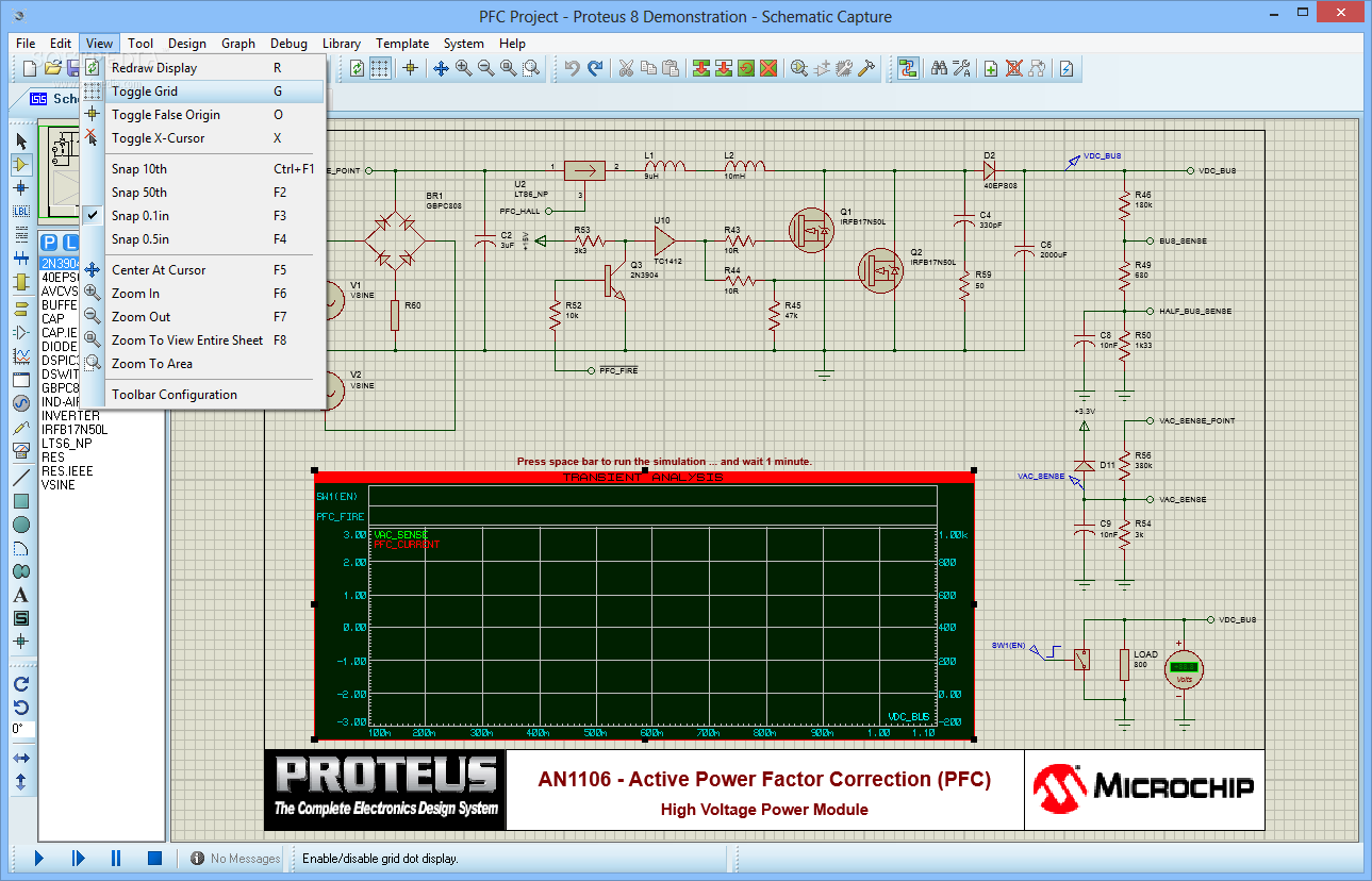
Proteus is a software used for electronic design automation mainly used for preparing schematics and designing PCBs. We will be using Proteus to design our PCB circuit and make PCB layout.
PROTEUS 8 PROFESSIONAL PCB LAYOUT FREE
There are many designing software available for designing PCBs such as Express PCB, Eagle PCB, PCBWeb Designer, Zenith PCB, PCB Elegance, Free PCB, Open Circuit Design and Proteus etc. It is simpler and has lesser chances of error, and takes lesser time to manufacture. We design our circuit’s layout using designing software, then the copper layout is prepared by etching and then solder the various components onto the board. Layout PCBs, on the other hand, are simpler to design. For example, connecting the pins and avoiding error in shot connections. Designing such PCBs is complex and can have many errors. The components are then attached with wires and soldered together. There are two types of PCBs on the basis of design, Dotted PCBs and Layout PCBs.ĭotted PCBs have dots available on the surface and components are inserted in these holes accordingly. They are composed of substrate and base materials in the form of a board with copper traces and various components attached to direct current through the circuit.

Printed Circuit Boards are the basic components of electronic systems.

PCB is the acronym for Printed Circuit Boards.


 0 kommentar(er)
